Product
Summary of Z20 Valve Electric Device
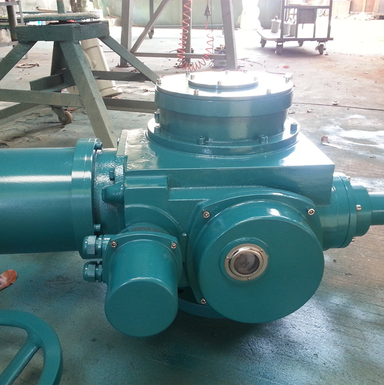
Z20 electric actuator, abbreviated as Z-type electrical equipment, is the driving equipment for valve opening, closing or regulating control. Z-type electric installation is suitable for gate valve, globe valve, diaphragm valve, plunger valve, throttle valve, water gate, etc. It can be used in open stem valves or dark stem valves. Z20 electric actuator has many advantages, such as full function, reliable performance, advanced control system, small size, light weight, convenient use and maintenance, etc. The valve can be controlled remotely, centrally and automatically. It is widely used in electric power, metallurgy, petroleum, chemical industry, paper making, sewage treatment and other industries.
II. Structure of Z20 Valve Electric Device
Z20 electric actuator is composed of motor, deceleration mechanism, moment control mechanism, travel control mechanism, opening indicator mechanism, hand-electric switching mechanism, handwheel and electrical parts. Its transmission principle is shown in the figure.
Note: Flameproof surface structure is added to the flameproof electrical part, and flameproof junction box and YDF flameproof valve motor are used. When installing, debugging and maintaining, the flameproof surface should not be damaged; the electrical cover should not be removed under explosive environment for live operation; the power supply must be cut off before opening the cover; the cover should be tightly fastened to ensure flameproof performance when reinstalling.
3. Shape and Connection Dimensions of Z20 Valve Electric Device
4. Z20 Valve Electric Device Hand-to-Electric Switching Mechanism:
For semi-automatic switching, the wrench handle should be switched manually, and the manual state should be automatically operated when it is changed to electric power. The utility model is composed of a handle, a switching part, a vertical rod, a clutch, a pressure spring, etc. When the handwheel is needed to operate, the handle is pushed to the manual direction, the switching parts raise the clutch and press the spring. When the handle is pushed to a certain position, the clutch is separated from the worm wheel and engages with the hand wheel. At the same time, the vertical rod is upright on the end face of the worm wheel under the torsion spring, which supports the clutch and does not fall. When the switch is completed, the clutch can be released and operated by a commission. When electric operation is needed, the motor will drive the worm wheel to rotate, and the vertical rod supporting the end face of the worm wheel will fall down. Under the action of the pressure spring, the clutch moves rapidly to the direction of the worm wheel and engages with the worm wheel. At the same time, it will be detached from the hand wheel to automatically realize the transition from manual to electric state.
Note: 1. Do not pull the switch handle when the motor is running!
2. Push (or pull) the handle in the direction of the arrow when switching. If the handle is not propelled in place, it should be pushed while turning the entrusted handle!
